

Pointer arrays are a useful tool for mapping peripheral registers to a driver. There are many advantages to using pointer arrays such as simplified initializations and the ability to generate a configuration table which promotes code reuse. Timer modules are one of the fundamental peripherals that are used in every embedded application. Timers are used to keep track of time, generate PWM signals and much more. In this post, the technique of using pointer arrays to map a timer peripheral will be examined for a common 16 bit microcontroller, keeping in mind that the techniques used can be applied to any type of microcontroller.
Before a driver can be written for any peripheral, the first step is a detailed examination of the datasheet. For this example, the datasheet reveals that there are five distinct timer channels each controlled by three registers. A timer, period and control register need to be configured in order to setup and operate the timer channel. The control register in this case is broken up into multiple functions such as start/stop the timer, clock selection and clock prescaler. The timer period register determines at what count the timer expires and then the timer register is the register that actually does the counting. Once equipped with this vital information it is very straight forward to setup a pointer array. Let’s examine how this could be done for the timer driver. Listing 1 demonstrates how the timer register (the register that counts) will be mapped using the pointer array.
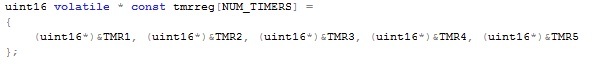
Listing 1: Timer Register Pointer Array
This declaration is declaring an array named tmrreg of constant pointers to volatile uint16’s. Notice that the declaration is read from right to left. This is critical in order to properly declare the pointer array as a constant yet still allow the compiler to know that the values that are being pointed to may change without software making the change. This also ensures that the actual pointers to our registers are constant and cannot be changed within the application. Each register type in the timer module would have their pointer arrays setup in this same form. In this case the TMR1, TMR2, etc are masks defined by the compiler to be the memory location of the register. The other register types would use their own mask definitions. The pointer array has the explicit advantage of allowing the developer to create a loop through which each channel register can be setup. For example, during initialization, if the developer wanted to clear the timer registers the code in Listing 2 could be used.
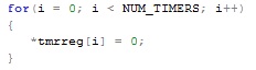
Listing 2: Clearing Timer Register on 5 Timers
In this case the pointer at index i is dereferenced and the register that is being pointed to is set to 0. Initially this looks like a lot of extra work with very little advantage. After all, the developer may want to setup each timer differently. This is where the pointer arrays greatest power is! By setting up the registers to a peripheral in this manner a configuration table can be developed as part of the initialization. The configuration table would contain information about each timer and how it should be configured. The details of creating a configuration table will be discussed in the next post. For now, a look at what the timer initialization code looks like is essential. The initialization function will be setup to clear the timer register, set the period and control registers with the data stored in the configuration table. Instead of accessing each register individually and creating application specific initialization functions, generic code is used which can be found in Listing 3. During initialization, the code loops through the configuration table and sets up each register according to the table.
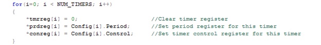
Listing 3: Timer Initialization
The array of pointers contains, well, pointers. This requires that each location be dereferenced in order to access the peripheral register. Beyond that the initialization function is nothing more than reading a configuration value from a table and stuffing it into the register. The code is not only compact but very easy to read. In order to see how each timer is configured, the engineer would simply look at the configuration table! No modification to the driver is required which makes this code easily reusable in other applications. Next time a look at creating configuration tables and expanding upon the initialization function to include setup of interrupts and interrupt priorities will be explored.


