

There are many advantages to using configuration tables to initialize an MCU’s registers. The most prevalent is that a configuration table displays the peripheral module as a channel with its entire configuration values explicitly defined. From a simple glance at a configuration table, an engineer can tell that timer one is setup for one millisecond intervals instead of having to consult the datasheet to understand what “PR1 = 0x15U;” is setting. This post will build upon the previous post on timers to demonstrate how a configuration table can be setup for a timer module.
Any peripheral configuration table should include a channel in addition to any useful, configurable values that may change from application to application. For the timer module, values that could be included are timer period, control register values, enabling and disabling the timer, in addition to setup of timer interrupts with their priority. The first step in setting up a configuration table is to create an enumeration that defines the timer module channels. In this example, the MCU will contain five separate and distinct timer modules. The example enumeration can be found in Listing 1.
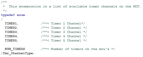
Listing 1: Timer Channel Enumeration
The second step in creating the configuration table is to define a structure that includes not only the timer channel but also the features of the timer module that will be configured by the table. While most microcontrollers will have similar features, they may vary slightly from one chip manufacturer to the next. Using the example timer features, a structure has been defined in Listing 2 that demonstrates what features to include in the configuration.
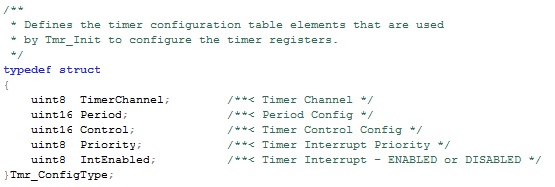
Listing 2: Timer Configuration Structure
Finally, the only step remaining is to populate the actual configuration that will be used to initialize the peripheral. The table is an array of the Tmr_ConfigType structure. Each element of the array defines the configuration for a single timer channel. The configuration table contains all of the basic information required to setup the timer peripheral. An example configuration table for the timer can be found in code Listing 3.
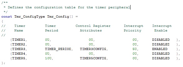
Listing 3: Timer Configuration Table
In this example only TIMER3 has interrupts enabled with the intent that it is the primary system timer. The timer period in this case is mask defined with the value that the timer period register would need to in order to achieve the desired period. While this requires knowledge of what the register should be, another approach would be to define this as desired interval and have the driver calculate the period register based on selected clock options.
While using configuration tables does increase the flash usage of the code and add some overhead to the initialization of registers, the advantage of being able to look at the table and instantly know how the device is configured greatly outweighs the disadvantages.
At this point, the configuration table can be passed to the Tmr_Init function to setup the peripheral; however, an examination of the driver code from the last post shows that the interrupt priorities and enabling/disabling the interrupt are not currently handled by the driver. Code to enable/disable the interrupt is pretty straight forward and can be found in code Listing 4.
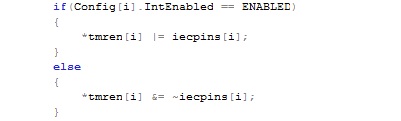
Listing 4: Timer Interrupt Setup
In this example, interrupt enable bit is simply checked to see if it is enabled or disabled. The pointer array contains the register that controls the interrupt. The iecpins array is simply being used to toggle the appropriate bit that corresponds to the particular timer interrupt. Code Listing 4 would be inserted into the for loop in Tmr_Init from the last post. The only piece missing would be the setup of the interrupt priority. It will be left as an exercise for the reader to add this to these techniques for their own MCU of choice.
The reader may feel that setting up configuration tables and initialization functions that read them are inefficient and contain too much overhead. The initialization functions contain looping code which provides a time overhead for setting up the peripheral. The advantage is that this code is usually only ran once, making the fact that it may take longer to run a trivial complaint. The advantage of having code that is easy to read and is very explicit as to how the peripheral is being setup greatly outweighs the startup performance hit, which is inconsequential if one is using a modern day microcontroller. When coupling this fact with the ability to easily reuse the code, using pointer arrays and configuration tables offer a developer essential tools for competing in a development environment which is often short on time and money.


