

The use of printf with an embedded systems based on a microcontroller has been generally not recommended as an industry best practice. A few reasons to avoid the use of printf is that it can usually inefficient, is a blocking function and interrupts the real-time behavior of the embedded system. The truth though is that printf is a critical debugging tool for an embedded system. One way that printf can be improved upon is to rewrite it using a circular buffer that utilizes interrupts. This article will explain the process to do this and the example code can be downloaded at the link below.

Step 1 – Define the printf function
The first step to defining a custom printf function to decide on how to name the new function so that it won’t conflict with library functions and to understand how to handle the printf parameter list. Since for an embedded system we are interested in using printf for debug data defining a new function named Debug_printf is a good first step. The standard printf function requires a constant char * to be passed to it, which is the string to output, along with a variable list of arguments. The variable list of arguments is handled by the library stdarg.h. The use of variable arguments is defined in the function parameter list by using three periods. The definition of the new printf function can be seen in Figure 1.
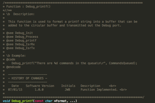 Figure 1 – Debug_printf definition
Step 2 – Define the local variables
There are a number of variables that will be needed in order to format the printf string and then push it onto the transmit circular buffer. The first variable is a local buffer array that stores the formatted printf string. Next, there is a variable argument list variable named Args. Args stores the arguments that are passed into the function. Length stores the size of the final string once it has been formatted. TxChar is just a variable used to get the first character to transmit on the serial device and i is just a loop variable. All of the variables needed for Debug_printf can be found in Figure 2.
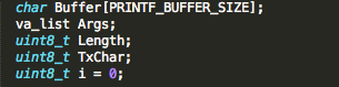 Figure 2 – printf function variables
Step 3 – Format the printf string
Generating the final formatted printf string can take a little bit of work but thankfully there are C library functions that can be used to perform most of the work. The first helper, va_start, is a macro that takes the variable argument list and the string pointer and prepares the Args list for formatting. Next, vsprintf is used to take the Format and the argument list and convert them into a final string that is stored in Buffer. Finally, the va_end macro is called to end the variable list and allow it to be returned. The resultant code is fairly straight forward and can be seen in Figure 3.
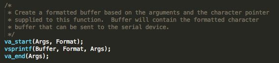
Figure 3 – Formatting the printf string to store in Buffer
Step 4 – Push Buffer onto a circular buffer
Once the final string has been formatted a standard printf function would just started to sequentially transmit the buffer out over the serial device. The transmission is usually done in a blocking fashion so that no other code is executed until the entire string has been transmitted. Transmitting in this way obviously can and will affect the real-time performance of the system. The longer the string, the worse the response time will get. To improve the real-time performance, the Buffer can be pushed onto a circular buffer that handles serial transmission in an interrupt driven fashion. To learn more about circular buffers please see the post “Open Source Circular Buffers”.
Since Buffer is a formatted string, strlen can be used to determine how many characters are present in the string. With that information, a simple loop can be used that calls CBUF_Push to push each character onto the buffer. The procedure to implement the transfer can be seen in Figure 4.
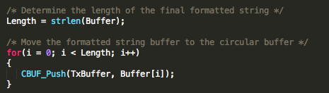
Figure 4 – Copy Buffer to the circular Tx buffer
Step 5 – Kickoff the transmission
The transmit interrupt won’t fire until the first character has been successfully transmitted. In order for that to happen the Debug_printf function needs to send the first character to the UART driver. To do this, the first character needs to be popped off the circular buffer and sent to the UART transmit function. UART driver calls are beyond the scope of this article but from the example code and Figure 5, the general idea of what needs to be available to the printf function can be discerned.
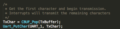
Figure 5 – Start transmitting
Step 6 – Fill in the transmit interrupt
The transmit interrupt is going to do the bulk of the heavy lifting once the first character has been transmitted. At that point the software will continue code execution while each character in the buffer is transmitted one at a time. A simple example of how this can be implemented can be seen in Figure 6. The interrupt basically clears the interrupt flag and then transmits the next character if the buffer is not yet empty.
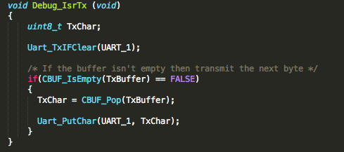
Figure 6 – Transmit ISR
Step 7 – Perform real-time measurements
Once the new Debug_printf function and associated functions are completed the code can now be tested. Sprinkle your application code with gpio toggles and measure how long it takes code to execute and respond to various events. Once the baseline measurements are completed start to sprinkle in the new debug function and monitor the timing measurements. For very basic output the real-time impact should be negligible. Don’t forget to stress test the system and gain an understanding of how far you can go before the real-time performance is impacted.


